Toyota Venza belongs to the class of mid-size crossovers (CUV - Crossover Utility Vehicle). This model for the North American market has been produced since November 2008 at the Toyota plant in Kentucky, USA. A distinctive feature of the model is a unique body design that combines elegance and massive shapes, and a very high level of cabin comfort, which evokes a great feeling of luxury, spaciousness and freedom. The car was created on the basis of the Camry platform and largely borrows its technical stuffing. If we talk about the position of the car in the Toyota lineup, then it occupies an intermediate position between such popular models as the RAV4 and Highlander.
Information on the diagrams is relevant for Toyota Venza (GV10) models 2008, 2009, 2010, 2011, 2012, 2013, 2014, 2015, 2016, with 1AR-FE (2.7 l) and 2GR-FE (3, 5 l).
In the engine compartment
General layout of electrical equipment.

|
|
| 1 | Fuse and relay box |
| 2 | Engine control module |
| 3 | Transmission control module |
| 4 | Headlamp wiper relay |
| 5 | Brake actuator |
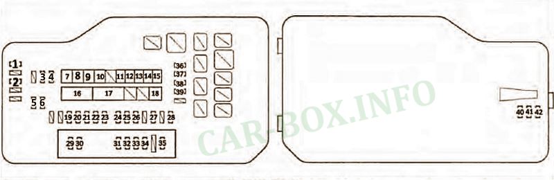
Fuse box

Located on the right side of the engine compartment, near the battery.

General view.
| Diagram | ||
|---|---|---|
|
||
| No. | Description | A |
| 1 | Connectors for additional equipment | 15 |
| 2 | Windshield wiper de-icer | 20 |
| 3 | ECM - INJ No. 1 | 15 |
| 4 | ECM - INJ No. 2 | 15 |
| 5 | ECM - EFI No. 2 | 15 |
| 6 | ECM - EFI No. 3 | 10 |
| 7 | Air conditioning system | 50 |
| 8 | ABS system, VSC system | 50 |
| 9 | (Models with 2GR-FE engine) Cooling fan | 50 |
| 10 | ABS system, VSC system | 30 |
| 11 | (Models with 1AR-FE engine) CDS FAN cooling fan | 30 |
| 12 | (Models with 1AR-FE engine) RDI FAN cooling fan | 30 |
| 13 | (Models with 2GR-FE engine) Cooling fan | 40 |
| 14 | Rear door electric drive | 30 |
| 15 | Rear door glass heater | 30 |
| 16 | Charging system, fuse circuit: HEATER, ABS # 1, ABS # 2, FAN MAIN, PBD, PR DEF, MIR HTR, DEICER | 120 or 140 |
| 17 | Electric power steering | 80 |
| 18 | ST / AM2 starting system | 30 |
| 19 | central locking | 20 |
| 20 | Steering wheel lock system | 20 |
| 21 | SEC HORN | 7.5 |
| 22 | "Multiplex" system, starting system | 7.5 |
| 23 | ALT-S charging system | 7.5 |
| 24 | "Entry & Start" system, engine management system, automatic transmission control system | 10 |
| 25 | Engine control module | 10 |
| 26 | Direction indicators and hazard warning lamps | 15 |
| 27 | SRS system, fuse chain: INJ # 1, INJ # 2 | 25 |
| 28 | Radio cassette | 25 |
| 29 | (Models with 2GR-FE engine) Air fuel ratio sensor | 20 |
| (Models with 1AR-FE motor) Fuse circuit: EFI # 2, EFI # 3 | 20 | |
| 30 | Sound signal | 10 |
| 31 | Low beam (left headlamp) | 15 |
| 32 | Low beam (right headlamp) | 15 |
| 33 | High beam (left headlamp) | 15 |
| 34 | High beam (right headlamp) | 15 |
| 35 | (Models with 2GR-FE engine) Fuse circuit: EFI # 2, EFI # 3 | 25 |
| (Models with 1AR-FE engine) Air fuel ratio sensor | 25 | |
| 36 | Interior lighting, power tailgate, gauges and indicators | 7.5 |
| 37 | Gauges and indicators, clock, radio, body electrical control unit, central locking remote control system, "Entry & Start" system, electric rear door, airbag and seat belt tensioner activation system for the front passenger | 10 |
| 38 | Audio and video system for rear passengers | 10 |
| 39 | Radio, navigation system | 15 |
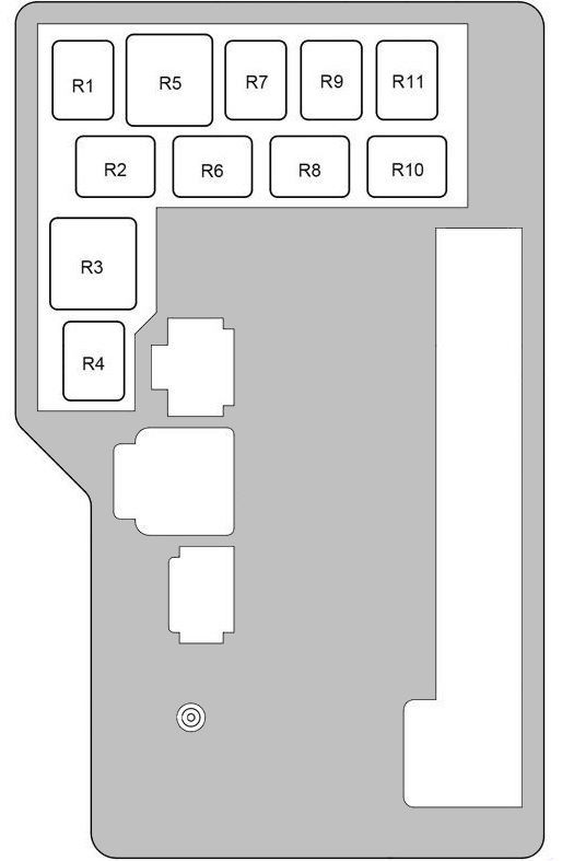
| The purpose of the relay in the block | |
|---|---|
|
|
| R1 | Anti-theft system (HORN) |
| R2 | Heated area for windscreen wiper blades (DEICER) |
| R3 | Empty |
| R4 | Brake light |
| R5 | Heated rear window |
| R6 | Starter |
| R7 | Electric cooling fan |
| R8 | Headlamps |
| R9 | Electric cooling fan |
| R10 | |
| R11 | Ignition (IG2) |
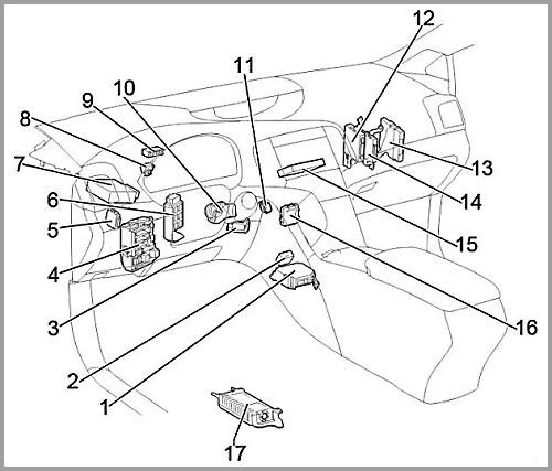
In the passenger compartment
General layout of electrical equipment in the Toyota Venza passenger compartment.
|
|
| 1 | Airbag module |
| 2 | Gear selector control module |
| 3 | Key transponder amplifier |
| 4 | Cabin fuse and relay box |
| 5 | Headlight range control module |
| 6 | Relay board |
| 7 | Power steering control module |
| 8 | Turn signal relay |
| 9 | Distribution connector |
| 10 | Steering lock actuator |
| 11 | Distribution connector |
| 12 | Air conditioner amplifier |
| 13 | Engine control module |
| 14 | Four-wheel drive control module |
| 15 | Expansion module |
| 16 | Active lighting control module |
| 17 | Audio amplifier |
Fuse box
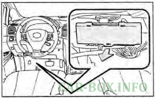
Located at the bottom of the dashboard on the driver's side.
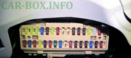
Access example.
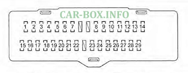
| Diagram | ||
|---|---|---|
|
||
| No. | Decoding | A |
| 1 | Power window regulator, rear right door | 20 |
| 2 | Power window regulator, rear left door | 20 |
| 3 | Power window regulator, front right door | 20 |
| 4 | Fog lamps | 15 |
| 5 | OBD self-diagnosis system | 7.5 |
| 6 | Power window regulator, front left door | 20 |
| 7 | Brake lamps, VSC system | 10 |
| 8 | Launch system | 7.5 |
| 9 | Steering wheel position sensor, air conditioning, power windows | 7.5 |
| 10 | Automatic all wheel drive system | 7.5 |
| 11 | Heated front seats | 20 |
| 12 | Electric sunroof | 15 |
| 13 | Tail and license plate lamps | 10 |
| 14 | Hazard alarm, radio tape recorder, clock, instrument cluster lighting rheostat, glove compartment lighting, steering wheel switches, rear side mirror heater, seat heater, VSC system, automatic transmission selector lighting | 5 |
| 15 | Multiplex system. electric sunroof, electric rear door, seat heater, automatic all wheel drive system, radio, automatic high beam control system | 10 |
| 16 | Rear door window washer | 15 |
| 17 | Air conditioning system | 10 |
| 18 | Windshield washer | 20 |
| 19 | VCS system. automatic headlight position correction system, vehicle longitudinal movement sensor, steering wheel position sensor, automatic transmission selector lock system, tire pressure monitoring system, automatic transmission control system, electric steering column | 7.5 |
| 20 | Navigation system, reversing lights, charging system, hazard warning lights, multifunction display | 10 |
| 21 | windshield wiper | 30 |
| 22 | Rear door glass cleaner | 15 |
| 23 | Engine management system, steering wheel lock system, entry & start system, SRS system, airbag activation system and front passenger seat belt pretensioner | 10 |
| 24 | Measuring instruments and indicators, multifunction display, "Multiplex" system | 7.5 |
| 25 | Power side rear-view mirrors | 7.5 |
| 26 | Automatic transmission selector locking system | 7.5 |
| 27 | Connectors for additional equipment | 15 |
| 28 | Radio, audio, video system for rear passengers | 7.5 |
| 29 | Heated side mirrors | 10 |
| Additional fuses and relays on the side of the block | |

|
|
| No. | Description |
| R1 | Fog lamp relay |
| R2 | Side lamps relay |
| R3 | Auxiliary relay (ACC) |
| R4 | Reserve |
| R5 | Ignition (IG1) |
| 1 | Electric seats 30A |
| 2 | Reserve |
Relay box
Located to the right of the main unit.
| Diagram | |
|---|---|

|
|
| No. | Description |
| R1 | Interior lamp |
| R2 | Rear fog lamp |
| R3 | Empty |
| R4 | Ignition (IG1 #2) |
Toyota Venza body electrical equipment
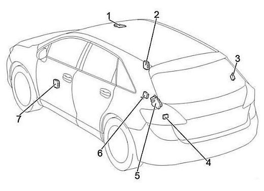
Location of components:
- Sunroof control module;
- Right mirror control module;
- Receiver for central locking;
- Distribution connector;
- Module for controlling the luggage compartment door;
- Control module for body electrical equipment (in the absence of a luggage compartment door with an electric drive);
- Left mirror control module.
