Most of the electrical circuits in the electrical equipment of the Japanese minivan are protected by fuses. Powerful current consumers are connected via relays. Protective elements are installed in distribution boxes, which are located in the engine compartment and the passenger compartment.

The information provided in the diagrams refers to Toyota Verso (R20) 2009, 2010, 2011, 2012, 2013, 2014, 2015, 2016, 2017 models.
In the engine compartment
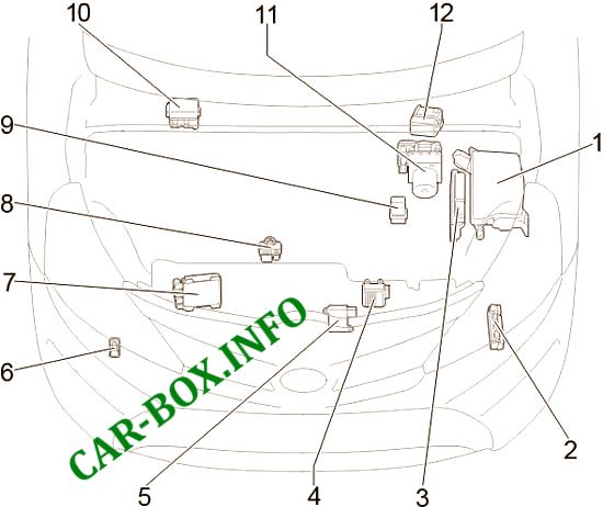
Location of components: 1. Fuse box; 2. Glow plug control unit (1AD-FTV, 2AD-FTV); 3. Engine control unit; 4. Transmission control unit; 5. Cooling fan control unit; 6. Relay for headlight cleaners; 7. Injector control unit; 8. Glow plug control unit (1WW); 9. Glow plug relay; 10. Relay box (left hand drive); 11. Brake system control unit; 12. Relay box (right hand drive).
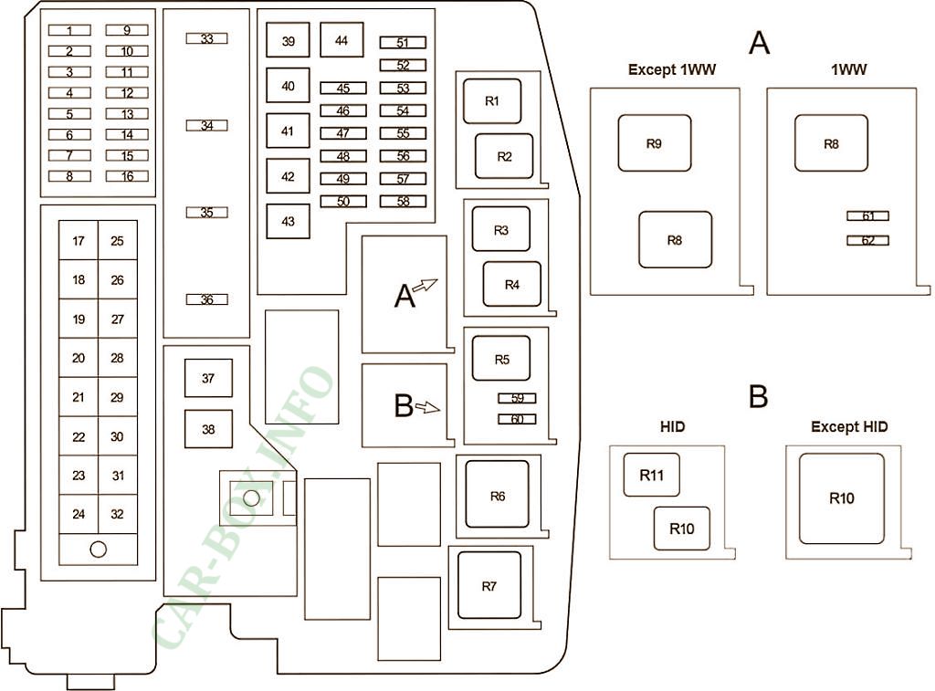
Fuse box
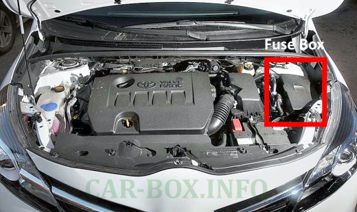
Photo location.
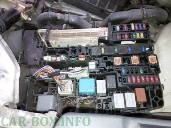
General view.
| Diagram | ||
|---|---|---|
|
||
| No. | Decoding | A |
| 1 | Luggage compartment lamps, vanity mirror lamps, front door step lamps, reading / interior lamps, door sill lamps | 10 |
| 2 | before June 2014: Audio, navigation, parking assistance | 20 |
| from June 2014: Audio, navigation, parking assistance | 15 | |
| 3 | Gauges, body ECM, steering sensor, locking system, remote control, smart system and keyless access | 10 |
| 4 | Empty | - |
| 5 | Intelligent & Keyless Access, Air Conditioning, Power Windows | 10 |
| 6 | Multiport fuel injection system / sequential multiport fuel injection system | 7.5 |
| 7 | Body electrical control unit | 25 |
| 8 | Empty | - |
| 9 | Multiport fuel injection system / sequential multiport fuel injection system | 15 |
| 10 | Steering column lock system | 20 |
| 11 | Multiport fuel injection system / sequential multiport fuel injection system | 20 |
| 12 | Launch system | 30 |
| 13 | Electronic throttle control system | 10 |
| 14 | Direction indicators (hazard warning lights) | 10 |
| 15 | Empty | - |
| 16 | Launch system | 7.5 |
| 17 | except 1WW: Air conditioning system | 50 |
| 18 | ABS, TRC, VSC, Hill Start Assist | 50 |
| 19 | Diesel: Cooling fan | 30 |
| 20 | Cooling fan | 40 |
| 21 | Headlamp washers | 30 |
| 22 | Fuses: "ECU-IG NO.2", "HTR-IG", "WIPER", "RR WIPER", "WASHER", "ECU-IG NO.1", "ECU-IG NO.3", "SEAT HTR "," AM1 "," DOOR "," STOP "," FR DOOR "," POWER "," RR DOOR "," RL DOOR "," OBD "," ACC-B "," RR FOG "," FR FOG "," DEF "," TAIL "," SUNROOF "," DRL " | 120 |
| 23 | Empty | - |
| 24 | Empty | - |
| 25 | Empty | - |
| 26 | except 1WW: Fuses: "H-LP LH LO", "H-LP RH LO", "H-LP LH HI", "H-LP RH HI" | 50 |
| 1WW: Fuses: "HORN", "IG2", "FUEL PMP" | 50 | |
| 27 | except 1WW: Fuses: "EFI MAIN", "IGT / INJ", "HORN", "IG2" | 50 |
| 1WW: Fuses: "H-LP LH LO", "H-LP RH LO", "H-LP LH HI", "H-LP RH HI" | 50 | |
| 28 | except 1WW: Fuses: "EFI NO.1", "EFI NO.2", "EFI NO.3", "EFI NO.4" | 50 |
| 1WW: Fuel heater | 50 | |
| 29 | VALVEMATIC system | 30 |
| 30 | except 1WW: Engine preheating system | 80 |
| 1WW: Electric power steering | 80 | |
| 31 | except 1WW: Electric power steering | 80 |
| 1WW: Engine preheating system | 80 | |
| 32 | Petrol: Charging system, fuses: "RDI FAN", "CDS FAN", "H-LP CLN", "ABS NO.1", "ABS NO.2", "HTR", "PWR OUTLET", "HTR SUB NO.1 "," HTR SUB NO.2 "," HTR SUB NO.3 "," ECU-IG NO.2 "," HTR-IG "," WIPER "," RR WIPER "," WASHER "," ECU-IG NO.1 "," ECU-IG NO.3 "," SEAT HTR "," AM1, DOOR "," STOP "," FR DOOR "," POWER "," RR DOOR "," RL DOOR " , "OBD", "ACC-B", "RR FOG", "FR FOG", "DEF", "TAIL", "SUNROOF", "DRL" | 120 |
| Diesel (except 1WW): Charging system, fuses: "RDI FAN", "CDS FAN", "H-LP CLN", "ABS NO.1", "ABS NO.2", "HTR", "PWR OUTLET" , "HTR SUB NO.1", "HTR SUB NO.2", "HTR SUB NO.3", "ECU-IG NO.2", "HTR-IG", "WIPER", "RR WIPER", " WASHER "," ECU-IG NO.1 "," ECU-IG NO.3 "," SEAT HTR "," AM1, DOOR "," STOP "," FR DOOR "," POWER "," RR DOOR ", "RL DOOR", "OBD", "ACC-B", "RR FOG", "FR FOG", "DEF", "TAIL", "SUNROOF", "DRL" | 140 | |
| 33 | Fuses: "IGN", "METER" | 15 |
| 34 | Horn, anti-theft system | 15 |
| 35 | Petrol: Multiport fuel injection system / sequential multiport fuel injection system | 20 |
| Diesel (up to Nov 2012): Multiport fuel injection system / sequential multiport fuel injection system | 30 | |
| 1WW: Fuel pump | 30 | |
| 36 | Gasoline: Multiport fuel injection system / sequential multiport fuel injection system | 15 |
| Diesel (except 1WW): Multiport fuel injection system / sequential multiport fuel injection system | 20 | |
| 37 | 1WW: Fuses: "EFI NO.1", "EFI NO.2", "EFI NO.4" | 50 |
| 38 | 1WW: Start-stop system | 40 |
| 39 | Auxiliary heater | 30 |
| 40 | Empty | - |
| 41 | Auxiliary heater | 30 |
| 42 | Air conditioning system | 50 |
| 43 | 1WW: Auxiliary heater | 50 |
| except 1WW: Auxiliary heater | 30 | |
| 44 | Empty | - |
| 45 | Auxiliary heater | 25 |
| 46 | ABS, TRC, VSC, Hill Start Assist | 30 |
| 47 | Empty | - |
| 48 | Empty | - |
| 49 | Empty | - |
| 50 | Power Outlet | 15 |
| 51 | except HID: Left headlamp (low beam) | 10 |
| HID: Left HID headlamp (low and high beam) | 15 | |
| 52 | except HID: Right headlamp (low beam) | 10 |
| HID: Right-hand HID lamp (low and high beam) | 15 | |
| 53 | Left headlamp (high beam) | 10 |
| 54 | Right headlamp (high beam) | 10 |
| 55 | except 1WW: Multiport fuel injection system / sequential multiport fuel injection system | 10 |
| 1WW: Cooling fan, Multiport fuel injection system / sequential multiport fuel injection system | 7.5 | |
| 56 | except 1WW: Multiport fuel injection system / sequential multiport fuel injection system | 10 |
| 1WW: Multiport fuel injection system / sequential multiport fuel injection system, start-stop system | 15 | |
| 57 | Launch system | 7.5 |
| 58 | to Nov 2012: Multiport fuel injection system / sequential multiport fuel injection system: EFI NO.3 | 7.5 |
| from Nov 2012: Multiport fuel injection system / sequential multiport fuel injection system: EFI NO.4 | 30 | |
| 1WW: Multiport fuel injection system / sequential multiport fuel injection system: EFI NO.4 | 20 | |
| 59 | Empty | - |
| 60 | from Nov 2012: Multiport fuel injection system / sequential multiport fuel injection system | 7.5 |
| 61 | 1WW: Cooling fan | 5 |
| 62 | 1WW: Cooling fan | 5 |
| Relay | ||
| R1 | Heated brush rest area (until November 2012 (FR DEICER)) | |
| Brake light (up to November 2012 (BRAKE LP)) | ||
| Cooling fan (from November 2012 (FAN NO.2)) | ||
| R2 | Cooling fan (FAN NO.3) | |
| R3 | Air Fuel Ratio (A / F) Sensor | |
| R4 | (IGT / INJ) | |
| R5 | Empty | |
| R6 | Diesel: Engine control unit (from November 2012 (EFI MAIN)) | |
| R7 | Headlamps (H-LP) | |
| R8 | Cooling fan (FAN NO.1) | |
| R9 | Cooling fan (up to November 2012 (FAN NO.2)) | |
| R10 | Dimmer (headlight switch) | |
| R11 | Empty | |
Relay box
#10 or 12 on the picture above.
| Diagram | |
|---|---|
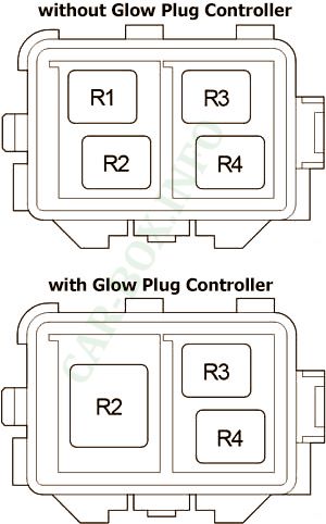
|
|
| No. | Appointment |
| 1 | Empty |
| 2 | Auxiliary heater (HTR SUB No. 1) |
| 3 | Auxiliary heater (HTR SUB No. 2) |
| 4 | Auxiliary heater (HTR SUB No. 3) |
In the passenger compartment
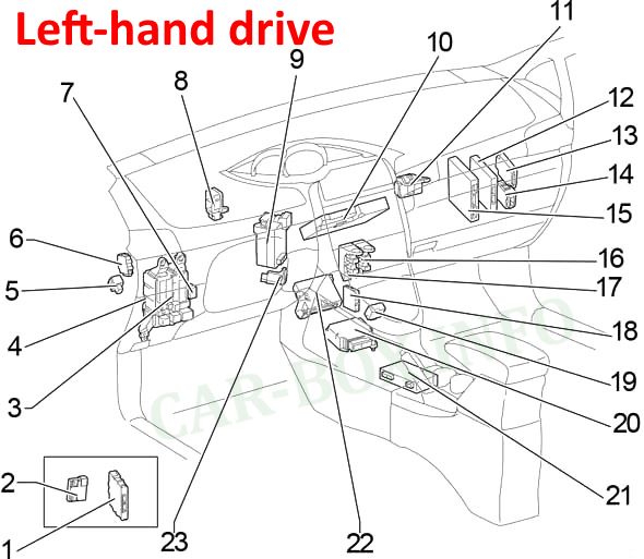
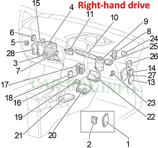
Component location: 1. Certification control unit; 2. Block ID code (intelligent entry and start system), Key transponder control block; 3. Fuse box; 4. Control unit for body electrical equipment; 5. Relay of brake lights; 6. Control unit for headlight range control; 7. Additional fuse box; 8. Distribution block; 9. Power steering control unit; 10. Navigation control unit; 11. Distribution block; 12. Engine and transmission control unit (Left hand drive); 13. Control unit for driver assistance systems; 14. Wiper relay; 15. Control unit for start-stop system; 16. Relay box No. 1; 17. Relay block # 2; 18. Parktronic control unit; 19. Control unit for blocking the gear selector; 20. Airbag control unit; 21. Multimedia system control unit; 22. Air conditioner amplifier; 23. Key transponder amplifier; 24. Direction indicator relay (alarm) (Right hand drive); 25 and 26. Double blocking relay (Right hand drive); 27 and 28. Engine and gearbox control unit (Right hand drive)
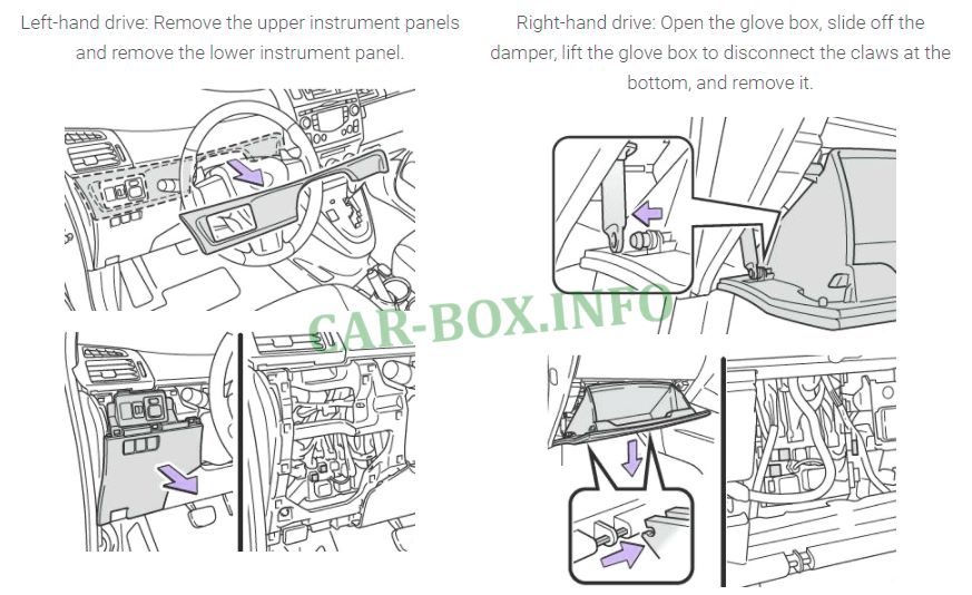
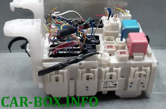
Fuse box
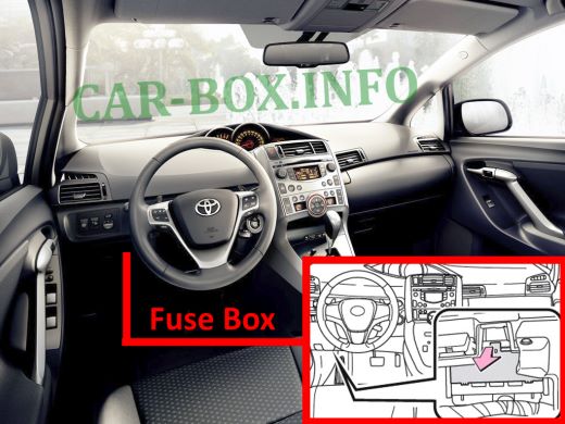
Photo location (LHD).

Access example.
| Diagram | ||
|---|---|---|

|
||
| No. | Decoding | A |
| 1 | Launch system | 7.5 |
| 2 | before Nov 2012: Front fog lamps | 15 |
| from Nov 2012: Front fog lamps | 7.5 | |
| 3 | Daytime Running Lamps | 7.5 |
| 4 | Fuses: "CIG", "ACC" | 25 |
| 5 | Mechanical door locking system | 25 |
| 6 | Panoramic sunroof blind | 20 |
| 7 | Stop lamps, high stop lamp, anti-lock braking system, VSC +, shift stop system, start system | 10 |
| 8 | Diagnostic connector | 7.5 |
| 9 | Reversing light, battery charging system, warning lamps, rear window defogger, airbag indicator, air conditioning system, Toyota parking sensor, Toyota parking sensor switch | 10 |
| 10 | Body ECM, electric cooling fan (s), shift stop system, steering sensor, cranking sensor, VSC +, headlight wipers, SEQUENTIAL switch, automatic headlight range control, electric power steering, low warning system tire pressure | 10 |
| 11 | Window washer, rear window washer | 15 |
| 12 | Rear window wiper | 15 |
| 13 | Wipers, vehicles with rain sensor wipers | 25 |
| 14 | Air conditioning system, autonomous interior heater | 10 |
| 15 | Seat heaters | 15 |
| 16 | Instrument cluster, stop / start system | 7.5 |
| 17 | Steering lock system, SRS airbag system, multiport fuel injection system / sequential multiport fuel injection system, automatic transmission, starting system | 7.5 |
| 18 | Rear fog lamps | 7.5 |
| 19 | Empty | - |
| 20 | Empty | - |
| 21 | Heated mirrors, heated rear window | 10 |
| 22 | Empty | - |
| 23 | Gearshift stop system, audio system, body ECU, electrical socket, exterior mirrors, Stop / Start system | 7.5 |
| 24 | Cigarette lighter fuse | 15 |
| 25 | Empty | - |
| 26 | Rear right power window | 20 |
| 27 | Rear left power window | 20 |
| 28 | Front right power window | 20 |
| 29 | Panoramic sunroof, auto-dimming interior mirror, smart system and keyless entry, audio system, stop / start system | 10 |
| 30 | Lights, Parking Assist (TOYOTA Parking Assist-Sensor) | 7.5 |
| 31 | Side lamps, license plate lamps, rear fog lamps, front fog lamps, manual headlamps range control, instrument cluster lamps, glove box lamp, switch lights, Toyota ECU parking sensor | 10 |
| Additional elements on the upper side of the block | ||
|---|---|---|
|
||
|
||

|
||
| No. | Protected circuit | A |
| 1 | Front left power window | 30 |
| 2 | Heated rear window, "MIR HTR" fuse | 30 |
| 3 | Empty | - |
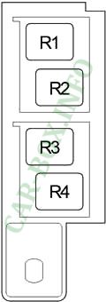
| Relay | ||
| R1 | Ignition (IG1) | |
| R2 | Jumper (automatic air conditioning) Heater (HTR) |
|
| R3 | Left hand drive : Direction indicators (hazard warning lights) | |
Relay box #1
#16 on the picture.
| Diagram | |
|---|---|
|
|
| No. | Description |
| R1 | Front fog lamps (FR FOG) |
| R2 | Auxiliary relay (ACC) |
| R3 | Daytime running lamps (DRL) |
| R4 | Panel (PANEL) |
Relay box #2
#17 on the picture.
| Diagram | |
|---|---|

|
|
| No. | Description |
| R1 | Starter (ST) |
| R2 | Rear fog lamp (RR FOG) |
| R3 | Power Outlets |
| R4 | Interior lamps |
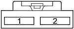
Auxilary fuse box
#7 on the picture.
| Diagram | ||
|---|---|---|
|
||
| No. | Protected circuit | A |
| 1 | Battery charging system | 7.5 |
| 2 | Empty | - |
Car Body

Location of components:
- Control unit for panoramic sunroof;
- Receiver for central locking;
- Receiver for tire pressure monitoring system
