
Most electrical circuits in this Japanese hatchback are protected by fuses, while high-draw components are powered through relays. Circuit protection devices are housed in junction blocks located in the engine compartment and passenger cabin.
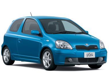
This information applies to 1998–2005 Toyota Vitz and Platz (chassis codes SCP10, SCP13, NCP10, NCP13, NCP15, SCP11, NCP12, NCP16; NBC platform) models equipped with 1.0L (1SZ-FE), 1.3L (2NZ-FE), or 1.5L (1NZ-FE) gasoline engines.
Location of Relays, Control Units, and Fuses
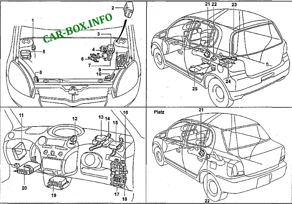
1 – Start-Stop system oil pump relay, 2 – Fuse box (models with Start-Stop system), 3 – Engine compartment relay block No. 2, 4 – Fuse box, 5 – ABS relay block, 6 – Starter control relay (Start-Stop system), 7 – ABS hydraulic unit / modulator, 8 – Right front SRS sensor, 9 – Engine compartment junction block, 10 – Left front SRS sensor, 11 – Start-Stop system control module, 12 – Central door locking relay, 13 – Keyless entry / central locking receiver, 14 – Vehicle Stability Control (VSC) module, 15 – Electric Power Steering (EPS) control module (2SZ-FE), 16 – Fuse box, 17 – Under-dash junction block, 18 – Fog lamp relay (RS models), 19 – SRS airbag control module, 20 – Engine Control Module (ECM/ECU), 21 – Shift lock control module, 22 – Deceleration G-sensor (ABS, 4WD), 23 – Fuel pump relay, 24 – DC-DC converter / transformer (Start-Stop system), 25 – Auxiliary battery (Start-Stop system).
Passenger Compartment
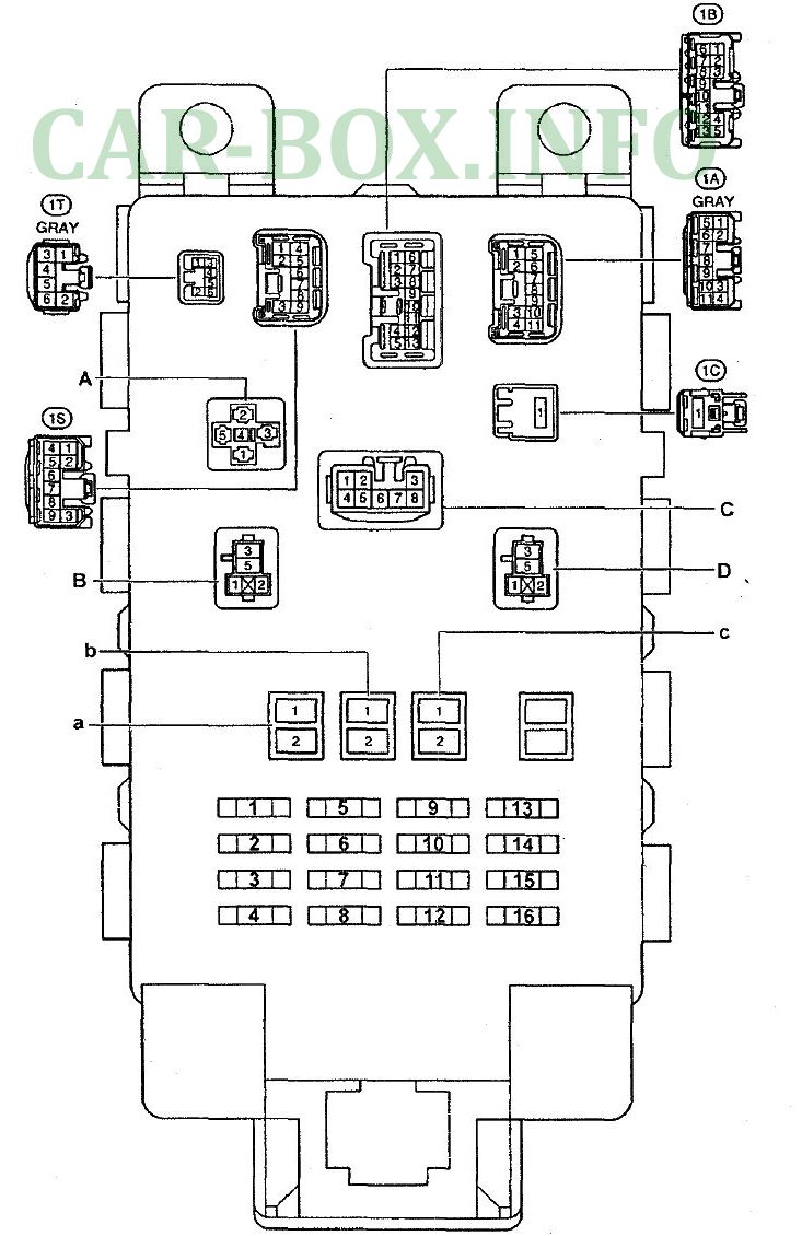
Under-dash fuse and relay assignments.
| Diagram | ||
|---|---|---|
|
||
| No. | Rating (A) | Protected Circuit / Component |
| 1 | 10 | Instrument cluster, turn signals, hazard warning lights, seat belt warning, key reminder |
| 2 | Not used | |
| 3 | 15 | Cigarette lighter, digital clock, multi-information display, instrument cluster, audio unit, power mirrors, seat belt warning, key reminder |
| 4 | 7.5 | Air conditioning and heater controls |
| 5 | 25 | Rear window defogger, heated mirrors |
| 6 | 20 | Windshield and rear window wipers/washers |
| 7 | 7.5 | ABS, instrument cluster, multi-information display, auxiliary heater, radiator and condenser cooling fans, SRS airbag system |
| 8 | Not used | |
| 9 | 25 | Central door locking system |
| 10 | 7.5 | Headlights (DRL models), rear fog light |
| 11 | Not used | |
| 12 | ||
| 13 | 7.5 | Parking/tail lights, instrument panel illumination, rear fog light, headlights-on warning chime, headlights, headlight leveling system |
| 14 | 20 | Not used (except RS) FOG LAMP 20A: Front fog lights (RS models from 10/2000) |
| 15 | 10 | Turn signals, hazard warning lights |
| 16 | 10 | Brake lights, engine management system, automatic transmission position indicators, ABS |
| A | Heater blower relay | |
| B | Main ignition power relay | |
| C | Turn signal / hazard flasher relay | |
| D | Fuel pump relay | |
| a | 50 | AM1 ignition switch circuit |
| b | 30 | Power windows |
| c | 40 | Air conditioning and heater blower |
Engine Compartment
Fuse Box No. 1
Diagram:

|
||
| No. | Rating (A) | Protected Circuit / Component |
| 1 | 15 | Digital clock, instrument cluster, interior dome light, audio unit, lights-on warning chime, keyless entry receiver |
| 2 | 15 | EFI: Engine Control Module (ECM), automatic transmission shift indicator |
| 3 | 15 | Horn |
| 4 | 15 | Starter circuit and AM2 ignition switch circuit |
| 5 | 30 | Starter relay and ST ignition circuit |
| 6 | Not used | |
| 7 | 10 | Left headlight |
| 8 | 10 | Right headlight |
| 9 | 7.5 | A/C No. 2 (specific variants) |
| A | Cooling fan relay No. 2 | |
| B | Cooling fan relay No. 1 | |
| C | EFI main relay | |
| D | A/C compressor magnetic clutch relay | |
| E | Horn relay | |
| F | Auxiliary heater relay | |
| G | Not used | |
| H | Starter relay | |
| a | Not used | |
| b | 30 | RDI: Radiator and condenser cooling fans |
| c | HTR SUB1: Auxiliary heater | |
| d | Not used | |
Relay Box No. 2
Diagram:

|
||
| No. | Rating (A) | Function / Circuit |
| A | - | Headlight relay |
| B | - | Headlight dimmer relay (high/low beam) |
| C | - | Auxiliary heater relay |
| 1 | 10 | Right headlight (high beam) |
| 2 | 10 | Left headlight (high beam) |
High-Current Fusible Links
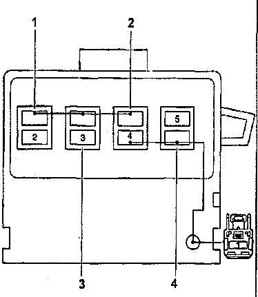
Mounted on the positive battery terminal.
| Diagram | ||
|---|---|---|
|
||
| No. | Rating (A) | Protected Circuit |
| 1 | 60 | Battery charging system, instrument cluster, engine management system, headlights, interior lighting, multi-information display, rear fog light, SRS airbags, starter and ignition systems, automatic clutch |
| 2 | 120 | Charging system (cold-climate models), headlights (non-DRL models), rear fog light, parking/tail lights, instrument illumination |
| 100 | Charging system (standard models), headlights (non-DRL models), rear fog light, parking/tail lights, instrument illumination | |
| 3 | 80 | Start-Stop system |
| 4 | 60 | ABS system |
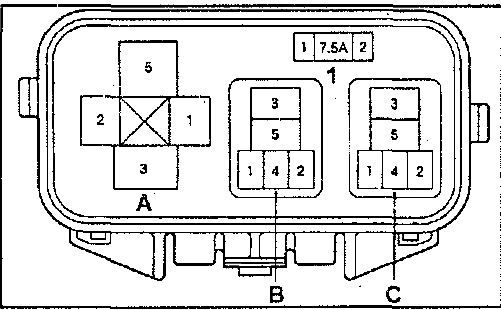
ABS Relay Box
Diagram:
|
| 1 – ABS fuse No. 3 (models without VSC) / Not used (models with VSC); A – Not used (models without VSC) / ABS MTR relay (models with VSC); B – ABS MTR relay (models without VSC) / ABS CUT relay (models with VSC); C – ABS SOL relay (models without VSC) / Not used (models with VSC). |