The compact MPV Ford C-Max has been produced in 2 generations since 2003. 1st generation was produced in 2004, 2005, 2006, 2007, 2008, 2009 and 2010. During this period, the car s-max was restyled. The 2nd generation was delivered to the markets in 2011, 2012, 2013, 2014, 2015, 2016, 2017, 2018, 2019 and to the present. In our material, we will show a description of the fuse boxes and relays ford with max with photos and block diagrams for the 1st and 2nd generation. The fuse responsible for the “cigarette lighter” is highlighted in bold.

The design of the blocks depends on the year of manufacture, and the purpose of the circuit elements may differ from the one presented due to a possible difference in the level of electrical equipment C Max.
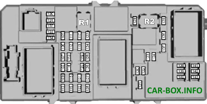
In the engine compartment
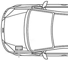
The main box of the engine compartment is located on the left side, under the protective cover.
Type 1
Models 2003 - 2010 release.
General view.
| Diagram | |
|---|---|
|
|
| № | Description |
| 1 | 40 / 60A Cooling fan |
| 2 | 80A Power steering |
| 3 | 60A Passenger compartment fuse box |
| 4 | 60A Passenger compartment fuse box |
| 5 | 80A Auxiliary heater |
| 6 | 60A Diesel: Glow plugs |
| 7 | 30A ABS, dynamic stability pump |
| 8 | 20A ABS, dynamic stability valves |
| 9 | 20A Engine control unit |
| 10 | 30A Fan of the climate control system |
| 11 | 20A Ignition lock |
| 12 | 40A Ignition relay 15l |
| 13 | 20A Starter |
| 14 | 40A Heated windshield, right side |
| 15 | 30A Cooling Fan Relay (Sigma - Non-A / C Options Only) |
| 16 | 40A Heated windshield, left side |
| 17 | 30A Electronic parking brake |
| 18 | 30A Inverter |
| 19 | 10A ABS module |
| 20 | 15A Sound signal |
| 21 | 20A Diesel: Auxiliary heater |
| 22 | 10A Power steering module |
| 23 | 30A Headlight washer |
| 24 | 15A Diesel: Auxiliary heater |
| 25 | 10A Ignition relay |
| 26 | 10 / 15A Automatic transmission control unit |
| 27 | 10A A / C compressor clutch |
| 28 | 10A Diesel: Glow plug control unit |
| 29 | 10A Separate climate control system |
| 30 | 3A Engine control unit, automatic transmission control unit |
| 31 | 10A Intelligent battery charging |
| 32 | 10A 2004-2007: 16V + VCT: Ventilation 2007-2010: Automatic transmission control unit |
| 33 | 10A Gasoline: Heated oxygen sensors Diesel: Air intercooler bypass valve |
| 34 | 10A Petrol: Injectors, ignition coils 2004-2007: Diesel: Fuel pump |
| 35 | 10A Engine control unit, valves |
| 36 | 10A Engine control unit |
| Relay | |
| R1 | Starter lock (automatic transmission) |
| R2 | Sound signal |
| R3 | Reversing lamps (automatic transmission) |
| R4 | Reserve |
| R5 | Diesel Preheating 16V + VCT: Ventilation |
| R6 | Main relay |
| R7 | Heated windshield |
| R8 | Ignition |
| R9 | headlight washer |
| R10 | Heater |
| R11 | Air conditioning |
| R12 | Cooling fan (without air conditioning) |
| R13 | Starter |
| R14 | Power Management Cooling Fan |
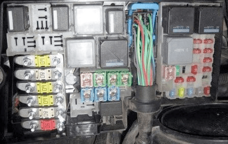
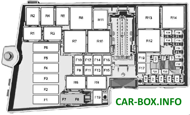
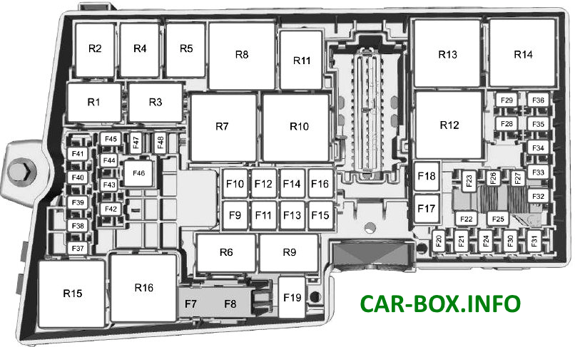
Type 2
Models 2011 - 2017 release
| Diagram | |
|---|---|
|
|
| № | Description |
| F7 | 40A ABS pump |
| F8 | 30A ABS valve |
| F9 | 20A Headlight washers |
| F10 | 40A Heater Fan |
| F11 | 30A Voltage quality module, start-stop system |
| F12 | 30A Relay, engine management system |
| F13 | 30A Starter relay |
| F14 | 40A Heated windscreen, right side |
| F15 | 25A Intercooler Fan - 1.0L EcoBoost, Cooling Fan Relay |
| F16 | 40A Heated windscreen, left side |
| F17 | 20A Combustion heater |
| F18 | 20A Windshield wipers |
| F19 | 5A Antilock Braking System, Dynamic Stability Control Module |
| F20 | 15A Buzzer |
| F21 | 5A Brake light switch |
| F22 | 15A Battery Monitoring System |
| F23 | 5A Relay Coils, Light Switch Control Module, Engine Control Module (15A), Gearbox Control Unit (15A), Gearbox Oil Pump (15A) |
| F24 | 20A Rear electrical outlet |
| F25 | 10A Exterior mirrors, electric |
| F26 | 15A Powertrain control unit |
| F27 | 15A Air conditioning compressor clutch |
| F28 | Reserve |
| F29 | 25A Heated rear window |
| F30 | 5A Powertrain control unit |
| F31 | Reserve |
| F32 | 10A EGR Valve, Swirl Control Valves, Heated Exhaust Oxygen Sensor (Engine Control Systems), Electronic Fan Control Module (Coil) Relay, Auxiliary Water Pump Module - 1.0L EcoBoost Engine |
| F33 | 10A Ignition coils |
| F34 | 10A Injectors |
| F35 | 5A Intercooler relay coil, 15A Fuel filter heating, 10A Water in fuel sensor (1.5L, 2.0L), ECM, ignition coils |
| F36 | 10A Powertrain control unit, 5A Active radiator shutter |
| F37 | Reserve |
| F38 | 15A Powertrain control module, transmission control module |
| F39 | 5A Headlamp control module |
| F40 | 5A Electric power steering |
| F41 | 20A Body electronics unit |
| F42 | 15A Rear window cleaner |
| F43 | 15A Headlight range control |
| F44 | 5A Adaptive cruise control |
| F45 | 10A Heated washer nozzles |
| F46 | 25A Power windows (front windows), Cooling fan |
| F47 | 7.5A Heated exterior mirrors |
| F48 | 15A Diesel combustion product filter evaporator |
| Relay decoding | |
| R1 | Intercooler fan |
| R2 | Sound signal |
| R3 | Diesel flue gas filter evaporator, Hybrid plant |
| R4 | Wiper |
| R5 | headlight washer |
| R6 | Wiper (high / low speed) |
| R7 | Heated windshield |
| R8 | Cooling fan |
| R9 | Reserve |
| R10 | Cooling fan |
| R11 | A / C compressor clutch |
| R12 | Cooling fan |
| R13 | Heater |
| R14 | The engine control unit |
| R15 | Starter |
| R16 | Ignition |
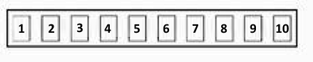
| Power fuse panel It is located next to the main one and consists of high power fusible links. |
|
|
|
| 1 | (80A) Power steering control module |
| 2 | (150A) Starter |
| 3 | (100A) |
| 4 | (50A) Multifunction control module |
| 5 | (80A) Auxiliary heater |
| 6 | (70A) Luggage compartment fuse / relay box |
| 7 | (60A) |
| 8 | (50A) Cooling fan motor control module |
| 9 | (50A) Multifunction control module |
| 10 | (60A) Glow plug control module |
In the passenger compartment

Fuse box located under the glove compartment, behind the trim. Mounted on two elements.
Type 1
Models 2003 - 2007 release.
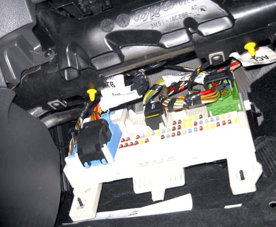
Access example.
| Diagram | |
|---|---|

|
|
| № | Description |
| 37 | 10A High beam left headlight |
| 38 | 10A High beam, right headlight |
| 39 | 20A Cigarette lighter , rear socket |
| 40 | 20A Sunroof |
| 41 | 20A Front passenger door electrical module |
| 42 | 7,5A Heated mirrors |
| 43 | 10A Electronic modules (battery powered) |
| 44 | 10A Diagnostic connector (OBD II) |
| 45 | 10A Daytime running lights |
| 46 | 10A Instrument cluster, multifunction electronic module (GEM) |
| 47 | 15A Washer pump, heated washer jets |
| 48 | 20A Low beam headlights, daytime running lights |
| 49 | 15A Light Switch |
| 50 | 20A Windshield wiper |
| 51 | 15A Fuel pump |
| 52 | 25A Heated rear window |
| 53 | 7.5A Side light on the left side |
| 54 | 7.5A Side light on the right side |
| 55 | 20A Driver's door electrical module, central locking |
| 56 | 20A Keyless entry system |
| 57 | 10A Siren anti-theft system |
| 58 | 15A Audio system (battery powered) |
| 59 | 25A Socket in the luggage compartment, trailer connector |
| 60 | 15A Low beam right headlight |
| 61 | 15A Low beam left headlight |
| 62 | 20A Electric driver's seat adjustment |
| 63 | 25A Windows |
| 64 | Reserve |
| 65 | 10A Airbags |
| 66 | 7.5A Headlight range control, low beam headlights, xenon module |
| 67 | 10A Immobilizer (WFS), instrument cluster (powered by ignition switch) |
| 68 | 7.5A Radio, instrument cluster |
| 69 | Fog light |
| 70 | 10A Electronic modules (powered by ignition switch) |
| 71 | 10A Daytime running lights |
| 72 | 25A Multifunction Electronic Module (GEM) |
| 73 | 7.5A License plate lighting |
| 74 | 15A Brake light |
| 75 | 10A Transmission control unit, electric gas pedal |
| 76 | 7.5A Electric parking brake |
| 77 | 25A Central locking relay |
| 78 | 15A Rear window wiper |
| 79 | 15A Electric folding mirrors |
| 80 | 10A Interior lighting, power mirrors |
| 81 | 20A Electrical module right rear door |
| 82 | 20A Module electrical equipment of the left rear door |
| 83 | 10A CD Changer, Rear Seat Entertainment (RSE) |
| 84 | 10A Reversing lamps, trailer connector |
| 85 | 10A Cooling system |
| 86 | 20A Heated seats |
| K1 | Heated rear window relay |
| K4 | Fuel pump relay |
| K5 | Daytime Running Lights relay |
| The fuse number 39, 20A, is responsible for the Ford C-Max cigarette lighter. | |
Type 2
Models 2007 - 2010 release.
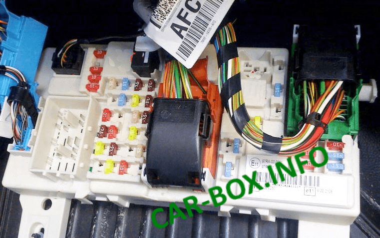
Access example.
| Diagram | |
|---|---|
|
|
| № | Designation |
| 100 | 10A Electronic modules (powered by ignition switch) |
| 101 | 20A Hatch, power driver's seat |
| 102 | 10A Heater control, steering column, diesel particulate filter, remote control receiver |
| 103 | 10A Battery power supply for external lighting controls |
| 104 | 10A Interior lighting, energy saving system |
| 105 | 25A Heated rear window |
| 106 | 20A Keyless entry system |
| 107 | 10A Instrument Cluster (Battery Powered) Diagnostic Connector (OBD II) |
| 108 | 7.5A Additional functions of the instrument cluster (audio and navigation systems) |
| 109 | 20A Cigarette lighter , rear socket |
| 110 | 10A Daytime running lights |
| 111 | 15A Petrol: Fuel pump |
| 112 | 15A Audio system (battery powered) |
| 113 | 10A Daytime running lights (side light) |
| 114 | 10A Instrument cluster, immobilizer |
| 115 | 7.5A Power supply for external lighting controls from generator |
| 116 | 20A Fog light |
| 117 | 7.5A License plate lighting |
| 118 | 20A Module electrical equipment left rear door |
| 119 | 15A Luggage compartment socket |
| 119 | 25A Socket in luggage compartment (with trailer module) |
| 120 | 20A Electrical module right rear door |
| 121 | 20A Heated front seats |
| 122 | 10A Airbags |
| 123 | 7.5A Heated mirrors |
| 124 | 7.5A Side light left side |
| 125 | 7.5A Side light on the right side |
| 126 | 20A Keyless Control System |
| 127 | 25A Power Windows |
| 128 | Not used |
| 129 | 20A Windscreen wiper |
| 130 | Not used |
| 131 | 15A Rear wiper |
| 132 | 15A Brake light |
| 133 | 25A Central locking relay, front passenger door electronics module |
| 134 | 20A Central locking, driver's door electrical module |
| 135 | 20A Daytime running lights |
| 136 | 15A Washer pump, heated washer jets |
| 137 | 10A Loudspeaker for turning on the emergency battery |
| 138 | 10A Engine control unit, transmission control unit, electric gas pedal |
| 139 | 10A High beam, right headlight |
| 140 | 10A High beam left headlight |
| 141 | 10A Reversing lamps, power mirrors |
| 142 | 15A Low beam right headlight |
| 143 | 15A Low beam left headlight |
| R1 | Fuel pump Relay |
| R2 | Not used |
| The fuse 109 20A is responsible for the cigarette lighter. | |
Type 3
Models 2011 - 2017 release.

Photo - example.
| Diagram | |
|---|---|
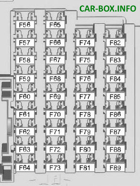
Diagram |
|
| № | Appointment |
| 56 | 20A fuel pump |
| 57 | Not used |
| 58 | Not used |
| 59 | 5A Transceiver passive anti-theft system |
| 60 | 10A Interior lighting, driver's door control unit, glove box lighting, ambient lighting, overhead control unit |
| 61 | 20A Cigarette lighter , rear socket |
| 62 | 5A Rain sensor, humidity sensor, auto-dimming interior mirror |
| 63 | 10A Adaptive cruise control system |
| 64 | Not used |
| 65 | 10A Power tailgate latch release |
| 66 | 20A Driver's door lock, double lock, fuel flap lock lock (2015-2018) |
| 67 | 7.5A Infotainment display, SYNC module, GPS module, telephone (Energi) |
| 68 | 15A Electric steering column lock |
| 69 | 5A Instrument Cluster |
| 70 | 20A Central locking |
| 71 | 7.5 / 10A Air conditioning system, heater control unit (mechanical air conditioner (Hybrid, Energi)) |
| 72 | 7.5A Steering wheel module |
| 73 | 5A Anti-theft system, diagnostic socket, battery of autonomous sound device |
| 74 | 15A high beam |
| 75 | 15A Front fog light |
| 76 | 10A Reversing lamps |
| 77 | 20A Windshield washer, rear window washer |
| 78 | 5A Ignition switch, start button, keyless entry system |
| 79 | 15A Hazard Switch, Radio, Navigation, Voice Control Module, DVD Player, CD Changer, Door Lock Switch |
| 80 | 20A Hatch |
| 81 | 5A Interior sensor, RF radio, sun blinds |
| 82 | 20A Glass washer pump |
| 83 | 20A Central locking |
| 84 | 20A Unlocking driver's door, double locking, unlocking fuel flap (2015-2018) |
| 85 | 7.5A Radio, Navigation, Passenger Airbag Deployment Switch, Seat Heating Switch, Parking Heater, Heater Control Unit (Mechanical Air Conditioning), Rear Wiper Relay, Auxiliary Heater, Adaptive Cruise Control |
| 86 | 10A Airbag and seatbelt control module, passenger presence recognition, passenger airbag indicator |
| 87 | 15A Heated steering wheel |
| 88 | 20A Voltage quality module |
| 89 | Not used |
| A fuse 61 for 20A is responsible for the cigarette lighter. | |
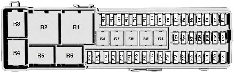
In the luggage compartment

Location.
| Diagram | |
|---|---|
|
|
| № | Decoding |
| 1 | 5A Hands-free tailgate opening |
| 2 | 10A Keyless Entry System |
| 3 | 5A Door handles on vehicles with keyless entry system |
| 4 | 25A Door module (front left) (power window, central locking, power folding mirrors, heated mirrors) |
| 5 | 25A Door module (front right) (power window, central locking, power folding mirrors, heated mirrors) |
| 6 | 25A Door module (rear left) (power window) |
| 7 | 25A Door module (rear right) (power window) |
| 8 | 10A Anti-theft system 25A Electric passenger seat |
| 9 | 25A Power driver's seat |
| 10 | 25A Power windows, Heated rear window |
| 11 | 5A Ignition relay |
| 12 | 10A Air Conditioning, 15A Battery Control Unit |
| 13 | 5A Instrument Cluster |
| 14 | 7.5 / 10A Infotainment display, GPS module (with start / stop module), Charging system |
| 15 | 15A Audio system |
| 16 | Not used |
| 17 | 10A Battery control unit |
| 18 | 15A Battery Control Unit - Fan |
| 19 | 15A Energi: Charging fan |
| 20 | Not used |
| 21 | 10 / 15A Smart connector |
| 22 | 10A Active noise cancellation |
| 23 | Not used |
| 24 | 30A DC / AC converter |
| 25 | 25A Power luggage compartment door |
| 26 | 40A Trailer module, AC / DC charging |
| 27 | 20 / 30A Heated rear window, Luggage compartment socket |
| 28 | Not used |
| 29 | 5A Blind Spot Monitoring System, Lane Lane Compliance System, Active City Stop System, Rear View Camera (without engine start / stop module), ignition (with engine start / stop system) |
| 30 | 5A Parking aid module |
| 31 | 5A Rear view camera |
| 32 | 5A DC / AC converter |
| 33 | 15A Rear wiper relay |
| 34 | 15A Heated driver's seat |
| 35 | 15A Heated passenger seat |
| 36 | Not used |
| 37 | 20A Sunroof sun protection panel |
| 38 | Not used |
| 39 | Not used |
| 40 | Not used |
| 41 | Not used |
| 42 | Not used |
| 43 | Not used |
| 44 | 10A Power mirrors |
| 45 | 7.5A Heated mirrors 5A Humidity sensor |
| 46 | 5A Blind Spot Monitor, Lane Lane Compliance System, Rear View Camera (with Engine Start / Stop System) 10A Fuel System |
| R1 | Ignition switch, terminal 15 |
| R2 | Heated rear window |
| R3 | Rear wiper, Fuel flap |
| R4 | - |
| R5 | Anti-theft alarm siren |
| R6 | Auxiliary relay, Rear wiper |
